This bench guide covers the exact parts, signal wiring, physical assembly, browser flashing, first calibration, and verification path for the LilyGo T-Display S3 build.
Inspect every solder joint and polarity before power-up. Never apply power to a galvanic oxygen cell. Calibrate only in known clean air and independently verify readings before using the analyser for diving.
Bill of materials
LilyGo T-Display S3 analyser parts
Use the bare board without fitted pin headers or a housing so it fits the printed enclosure. Match the battery plug polarity to the LilyGo socket rather than relying on wire colour.
Required parts
1 × LilyGo T-Display S3
1 × ADS1115 ADC module
1 × galvanic O2 cell and matching connector
1 × single-cell 3.7 V LiPo with matching 1.25 mm plug
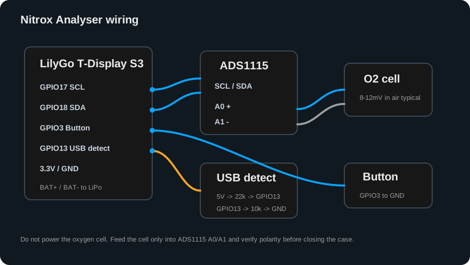
Connect the cell only to the ADS1115 differential inputs. The galvanic cell generates its own millivolt signal and must not be powered.
Inside reference
Component placement and cable routing
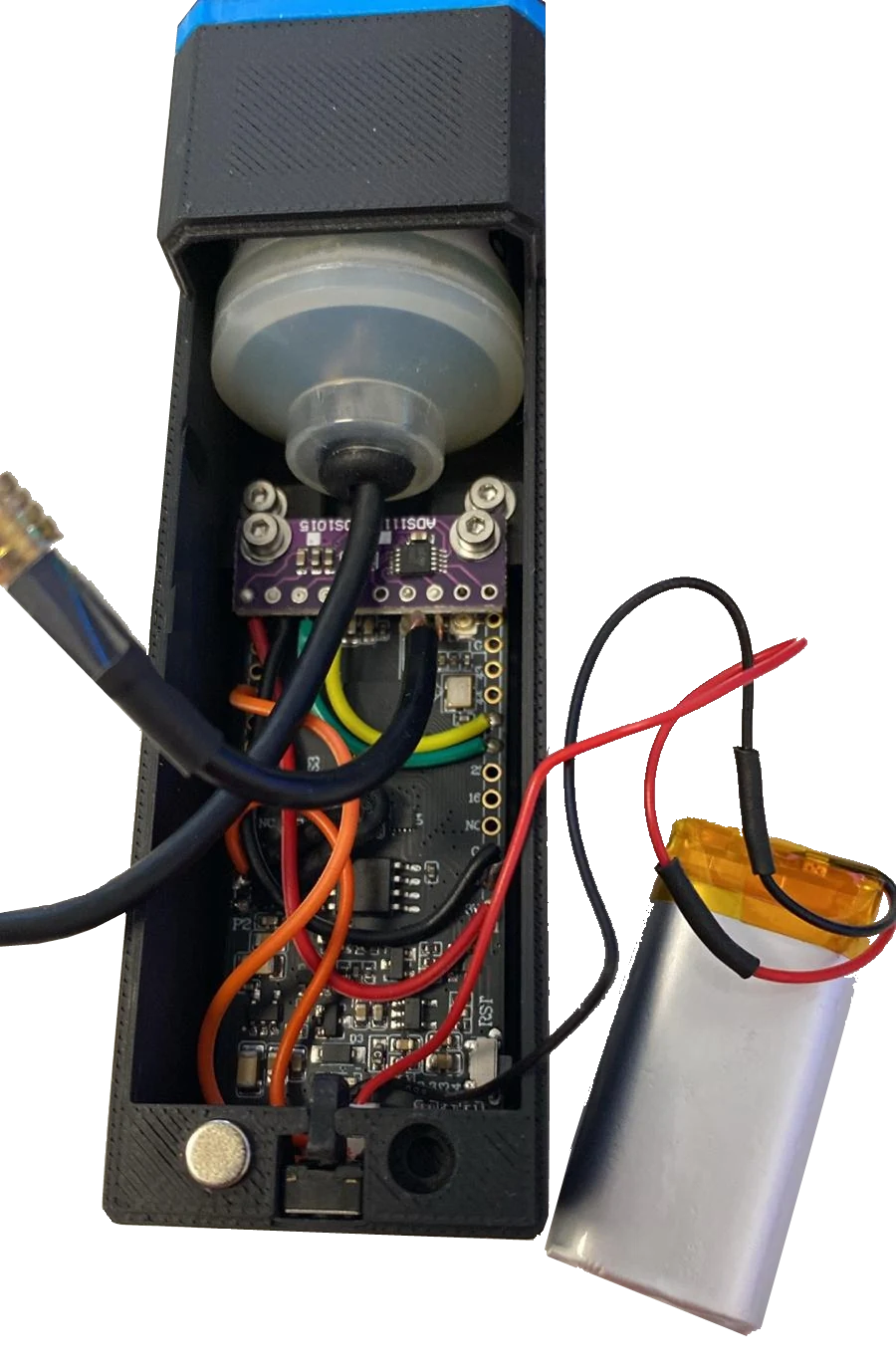
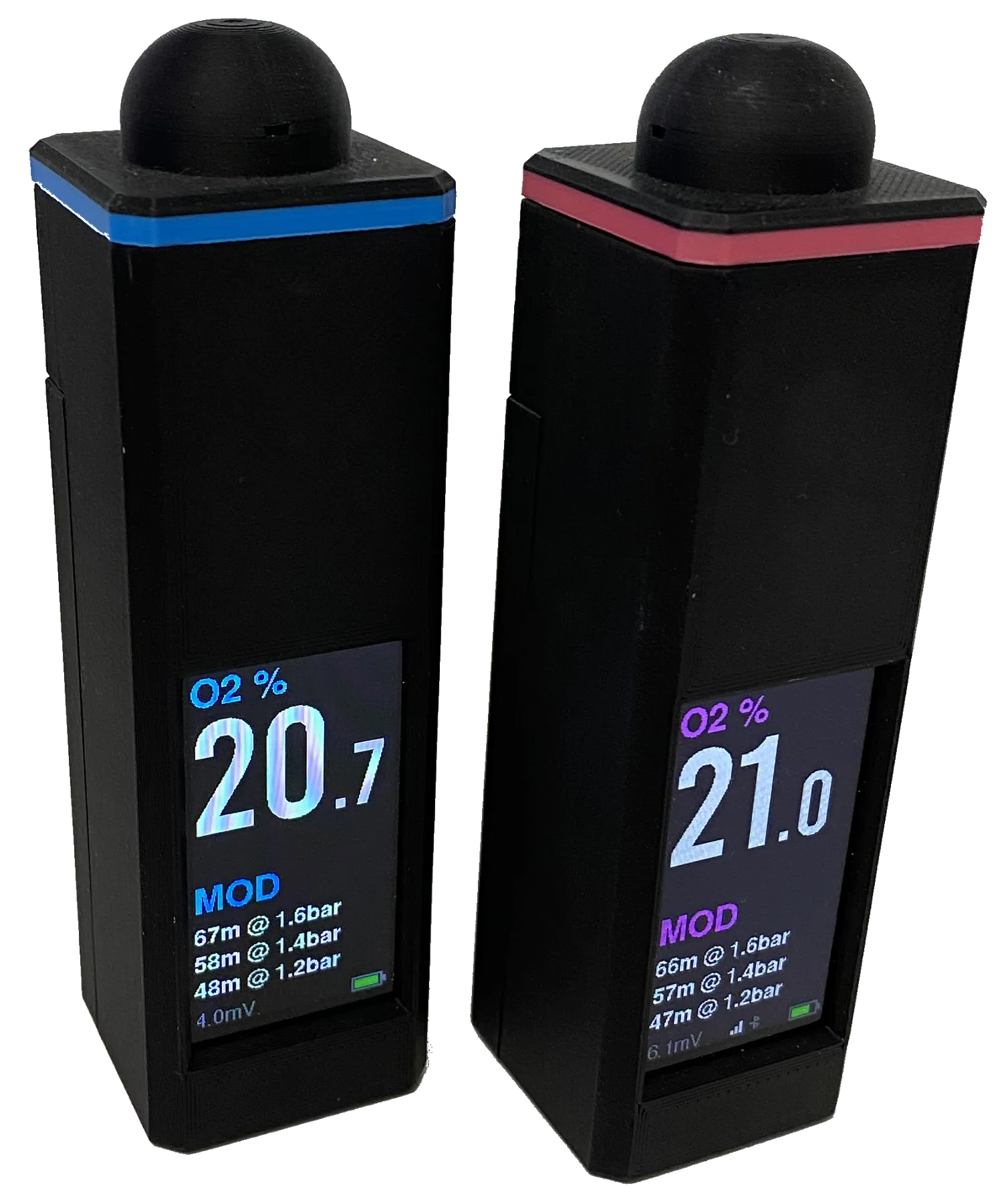
This completed build shows how the main parts fit inside the housing. Use the schematic above for the exact electrical connections. Detailed build photos will follow.
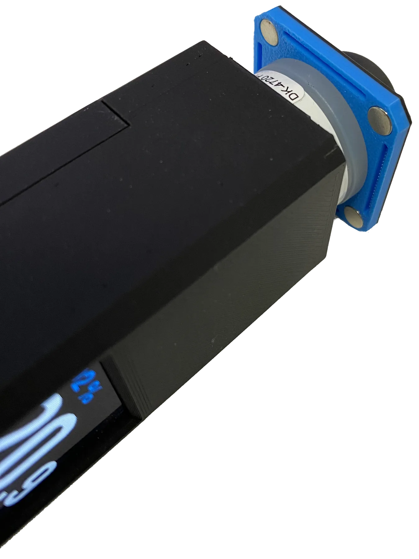
Prepare the housing.Print the released housing, install M2 heat-set inserts with controlled heat, and check all magnet polarities before pressing them in.
Housing, inserts, and magnets
Dry-fit the electronics.Position the LilyGo, ADS1115, cell connector, battery lead, and button. Confirm display, USB-C, sample opening, and lid clearances before soldering.
Check enclosure fit before wiring
Wire the ADS1115.Connect 3.3 V, GND, GPIO17 SCL, and GPIO18 SDA; tie ADDR to GND. Keep the millivolt signal wiring short and away from USB and battery conductors.
ADS1115 I2C and differential cell inputs
Connect the O2 cell.Connect cell positive to A0 and negative to A1. Add strain relief. Never drive either cell wire from a power rail or GPIO.
Check polarity and strain relief before closingO2 cell connection
Add button and USB divider.Wire the button from GPIO3 to GND. Wire 5 V through 22 kΩ to GPIO13 and 10 kΩ from GPIO13 to GND; never connect USB 5 V directly to a GPIO.
Measure the divider before connecting GPIO13Button and USB detection
Connect the battery last.Confirm connector polarity with a meter. Apply USB power first, check for heat or excess current, then connect the LiPo only after the board starts correctly.
Verify polarity at the LilyGo socketLiPo connection
Flash and configure.Use full install for a new board. Confirm the ADS1115 is detected, open the local Web UI, set label details, and pair the printer.
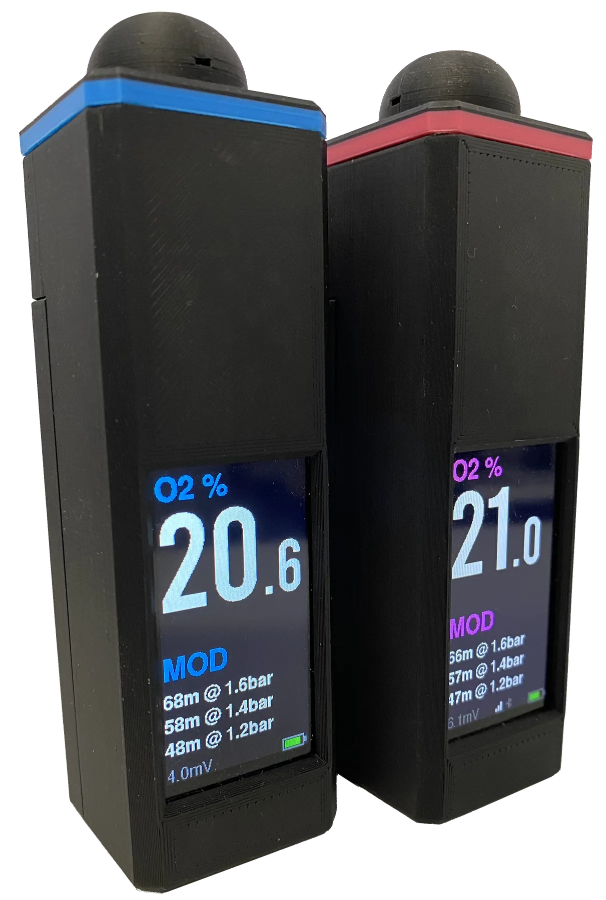
First boot and sensor status
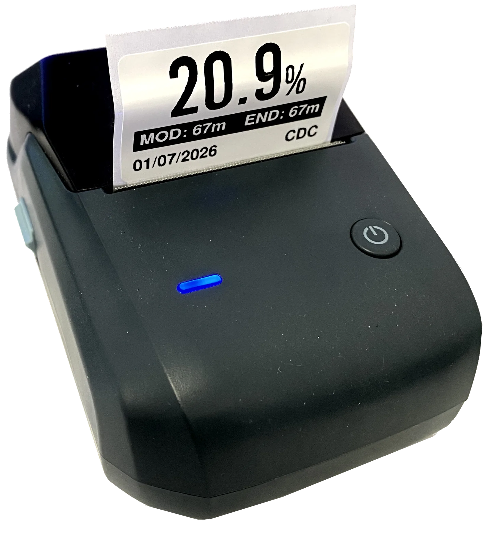
Calibrate and verify.Stabilise in clean air, calibrate once, compare with trusted equipment or known gas, and print a test label. Do not rely on the build until all checks pass.